Archives For 30 November 1999

The Raspberry Pi can easily be setup as an OpenVPN server. One common feature is to access servers or services on the remote network. Another use case is to provide a secure connection when you’re not at home.

You can do this by sending all traffic over the VPN connection, instead of only traffic for the remote servers. The idea is to connect your laptop to your OpenVPN server (this is encrypted by default) and access the internet from there. Whatever you send over the wifi connection, is encrypted by the VPN and thus safe. In the comments on the previous post there was someone trying to set this up. To help him solve the issue, I tested this myself, and decided to write a post showing how to do it because I really like the idea.

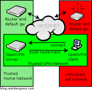
This is how it looks like: you’re on a untrusted network (red) and create a safe VPN connection (green) and all traffic will flow over the green network, to the also trusted home network (lighter green). People on the red network now cannot see the sites you visit.

OpenVPN secure wifi browsing

Here’s how to set it up:

  1. Allow the OpenVPN server to route ip traffic
  2. Tell the default gw where to send traffic for OpenVPN clients
  3. Send DNS servers to the VPN Clients
  4. Configure the OpenVPN Client
  5. Test your setup

Allow the OpenVPN server to route ip traffic
First of all, you need to allow the OpenVPN server to route packets.

sudo vim /etc/sysctl.conf

Add this line, or alter it if it already exists:

net.ipv4.ip_forward = 1

Then activate the change:

sudo sysctl -p

The change is now activated, and persistent.

Tell the default gw where to send traffic for OpenVPN clients
Another important step is to tell the default gateway in the home network (lighter green) where to send traffic for theOpenVPN clients. If you omit this step, this traffic gets lost. More info in this post. Short story: add this static route to your default gateway. If it’s Linux, you’d run:

sudo route add -net 10.8.0.0/24 gw 10.5.5.5

Assuming 10.5.5.5 is the ip address of the OpenVPN server. When your router is not Linux, check the manual on howto add a static route.

Send DNS servers to the VPN clients
Most ISP’s restrict the usage of their DNS servers to their own network. When you connect to Wifi, you probably receive some DNS servers via DHCP. When you connect to VPN and then send all traffic through the VPN, you are effectively using the network (and internet connection) of your VPN server and not the local network. The DNS-servers you received via DHCP might not work because you access them from another network. To solve this, configure the OpenVPN server to push public DNS servers to use. Alternatively you can also push some local DNS servers or the DNS servers of your ISP.

sudo vim /etc/openvpn/server.conf

Add or edit these lines:

push "dhcp-option DNS 8.8.8.8"
push "dhcp-option DNS 8.8.4.4"

These are Google’s public DNS servers. Just enter some DNS servers that work on the network of your OpenVPN server and that you are allowed to use.

Configure the OpenVPN client
I’m using Viscosity and all I have to do is enable a setting to send all traffic over the VPN connection.

viscosity_enable_all_traffic_over_vpn

Alternative way: It’s also possible to configure the ‘Send all traffic over VPN connection’ on the server-side instead of the client. Both has pros and cons, of course. To set it server-side set this option in the server config:

push "redirect-gateway def1"

Test your setup
The final step: test your setup! Make sure you’re connected through some other network than the one the OpenVPN server is in. Use some public Wifi service of connect over 3G. My iPhone can share its 3G connection and start a Wifi hotspot. My MacBook connects via Wifi, then does the OpenVPN connection to the Pi. The expected behavior is then to see the public ip address of the OpenVPN server’s internet connection, instead of the 3G ip address. Use a website like whatismyip.com to test this. Do this before connecting the VPN, and after. It should be different.

Enjoy your secure browsing experience!

Back in March I wrote a blog on how to create a network without a Virtual Router.  I received a lot of questions about it. It’s also a question that pops up now and then on the CloudStack forums. In the meanwhile I’ve worked hard to implement this setup at work. In this blog I’ll describe the concept of working with a CloudStack setup that has no Virtual Router.

First some background. In Advanced Networking, VLAN’s are used for isolation. This way, multiple separated networks can exist over the same wire. More about VLAN technology in general on this wikipedia page. For VLAN’s to work, you need to configure your switch so it knows about the VLAN you use. VLAN’s have an unique id between 1 and 4096. CloudStack configures this all automatically, except for the switch. Communication between Virtual Machines in the same CloudStack network (aka VLAN) is done using the corresponding VLAN-id. This all works out-of-the-box.

It took me some time to realize how powerful this actually is. One can now combine both VM’s and physical servers in the same network, by using the same VLAN for both. Think about it for a moment. You’re now able to replace the Virtual Router with a Linux router simply by having it join the same VLAN(s) and using the Linux routing tools.

Time for an example. Say we have a CloudStack network using VLAN-id 1234, and this network is created without a Virtual Router (see instructions here). Make sure you have at least 2 VM’s deployed and make sure they’re able to talk to each other over this network. Don’t forget to configure your switch. If both VM’s are on the same compute node, networking between the VM’s works, but you won’t be able to reach the Linux router later on if the switch doesn’t know the VLAN-id.

Have a separate physical server available running Linux and connect it to the same physical network as your compute nodes are connected to. Make sure the ip’s used here are private addresses. In this example I use:

compute1: 10.0.0.1
compute2: 10.0.0.2
router1: 10.0.0.10
vm1: 10.1.1.1
vm2: 10.1.1.2

The Linux router needs two network interfaces: one to the public internet (eth0 for example) and one to the internal network, where it connects to the compute nodes (say eth1). The eth1 interface on the router has ip-address 10.0.0.10 and it should be able to ping the compute node(s). When this works, add a VLAN interface on the router called eth1.1234 (where 1234 is the VLAN-id CloudStack uses). Like this:

ifconfig eth1.1234 10.1.1.10/24 up

Make sure you use the correct ip-address range and netmask. They should match the ones CloudStack uses for the network. Also, note the ‘.’ between the eth1 and the VLAN-id. Don’t confuse this with ‘:’ which just adds an alias ip.

To check if the VLAN was added, run:

cat /proc/net/vlan/eth1.1234

It should return something like this:

eth1.1234 VID: 1234 REORDER_HDR: 1 dev->priv_flags: 1
 total frames received 14517733268
 total bytes received 8891809451162
 Broadcast/Multicast Rcvd 264737
 total frames transmitted 6922695522
 total bytes transmitted 1927515823138
 total headroom inc 0
 total encap on xmit 0
Device: eth1
INGRESS priority mappings: 0:0 1:0 2:0 3:0 4:0 5:0 6:0 7:0
 EGRESS priority mappings:

Tip: if this command does not work, make sure the VLAN software is installed. In Debian you’d simply run:

apt-get install vlan

Another check:

ifconfig eth1.1234

It should return something like this:

eth1.1234 Link encap:Ethernet HWaddr 00:15:16:66:36:ee 
 inet addr:10.1.1.10 Bcast:0.0.0.0 Mask:255.255.255.0
 inet6 addr: fe80::215:17ff:fe69:b63e/64 Scope:Link
 UP BROADCAST RUNNING MASTER MULTICAST MTU:1500 Metric:1
 RX packets:14518848183 errors:0 dropped:0 overruns:0 frame:0
 TX packets:6925460628 errors:0 dropped:15 overruns:0 carrier:0
 collisions:0 txqueuelen:0 
 RX bytes:8892566186128 (8.0 TiB) TX bytes:1927937684747 (1.7 TiB)

Now, the most interesting tests: ping vm1 and vm2 from the linux router, and vice versa. It should work, because they are all using the same VLAN-id. Isn’t this cool? You just connected a physical server to a virtual one! 🙂

You now have two options to go from here:

1. Use a LoadBalancer (like Keepalived) and keep the ip’s on the VLAN private using Keepalived’s NAT routing. The configuration is exactly the same as if you had all physical servers or all virtual servers.

2. Directly route public ip’s to the VM’s. This is the most interesting one to explain a bit further. In the example above we’ve used private ip’s for the VLAN. Imagine you’d use public ip addresses instead. For example:

vm1: 8.254.123.1
vm2: 8.254.123.2
router1: 8.254.123.10 (eth1.1234; eth1 itself remains private)

This also works: vm1, vm2 and router1 are now able to ping each other. A few more things need to be done on the Linux router to allow it to route the traffic:

echo 1 > /proc/sys/net/ipv4/ip_forward
echo 1 > /proc/sys/net/ipv4/conf/eth1/proxy_arp

Finally, on vm1 and vm2, set the default gateway to router1; 8.254.123.10 in this example.

How does this work? The Linux router also answers arp requests for the ip’s in the VLAN. Whenever traffic comes by for vm1, router1 answers the arp request and routes the traffic over the VLAN to vm1. When you’d run a traceroute, you’ll see the Linux router appear as well. Of course you need to have a subnet of routable public ip’s assigned by your provider for this to work properly.

To me this setup has two major advantages:

1. No wasted resources for Virtual Routers (one for each network)
2. Public ip’s can be assigned directly to VM’s; you can even assign multiple if you like.

The drawbacks? Well, this is not officially supported nor documented. And since you are not using the Virtual Router, you’ll have to implement a lot of services on your own that were normally provided by the Virtual Router. Also, deploying VM’s in a network like this only works using the API. To me these are all challenges that make my job more interesting 😉

I’ve implemented this in production at work and we successfully run over 25 networks like this with about 100-125 VM’s. It was a lot of work to configure it all properly and to come up with a working solution. Now that it is live, I’m really happy with it!

I realize this is not a complete step-by-step howto. But I do hope this blog will serve as inspiration for others to come up with great solutions build on top of the awesome CloudStack software. Please let me know in the comments what you’ve come up with! Also, feel free to ask questions: I’ll do my best to give you some directions.

Enjoy!